REVIEW OF SCIENTIFIC INSTRUMENTS
VOLUME 70, NUMBER 9
SEPTEMBER 1999
Liquid nitrogen auto fill for temperature controlled cryogenic traps Paul F. Dennis, Alex Etchells, and David Blomfield Stable Isotope Laboratory, School of Environmental Sciences, University of East Anglia, Norwich NR4 7TJ, United Kingdom
共Received 26 January 1999; accepted for publication 8 June 1999兲 We describe the principle of operation and construction of an inexpensive, reliable system for the automated dispensing of liquid nitrogen from a single supply Dewar to multiple cryogenic traps. The system can be run under full computer control and in conjunction with existing designs of traps will allow unattended operation over long duty periods combined with programmed temperature cycles. © 1999 American Institute of Physics. 关S0034-6748共99兲03809-5兴
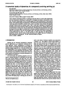
day兲 duty cycles. The system is cheap, robust and reliable, doesn’t require pressurized supply Dewars, and can be configured to deliver liquid nitrogen to several traps from one supply Dewar. In our application the traps and delivery system are under full computer control though the design will work as effectively using switched relay control with simple logic circuits. The principle of operation is shown schematically in Figs. 1共A兲–1共C兲. A small vessel 共250 mL兲, fitted with a oneway valve and nitrogen gas inlet and liquid nitrogen outlets, is located towards the bottom of the supply Dewar. The gas supply tube is connected via a three-way solenoid operated valve 共Clippard Minimatic™ ETO-3M兲 to: 共i兲 a nitrogen gas cylinder regulated with an output pressure of a little over 1 bar, and; 共ii兲 a vent, either via a one-way valve to air, or back into the liquid nitrogen Dewar head space. The insulated liquid nitrogen outlet tube connects to the trap Dewar. All the tubes are 6 mm-o.d.-nylon. When the solenoid valve is in the closed position the supply of nitrogen gas to the internal vessel is cut off and the vessel is vented allowing it to fill with liquid nitrogen 关Fig. 1共A兲兴. On demand the solenoid valve is switched pressurizing the internal container, closing the one-way valve, and forcing liquid nitrogen through the supply tube to the Dewar 关Fig. 1共B兲兴. It takes about 30 s to deliver 250 mL of liquid nitrogen to the trap Dewar after which the solenoid is programmed to close allowing the vessel to refill. If necessary the supply cycle is repeated until the trap Dewar is filled to the required level. The submerged vessel is constructed from a 250 mL wide necked high density polyethylene 共HDPE兲 bottle and lid. Fitted into the lid is a 20 mm o.d.⫻80-mm-long acetyl copolymer rod drilled through with an inside diameter 共i.d.兲 of 14 mm to a depth of 75 mm and a final bore of 8 mm. A 12 mm stainless steel ball bearing is located in the tube and rests on the drill chamfer at the base of the 14 mm bore. This provides a reliable one-way seal that is effective when submerged under liquid nitrogen. The nitrogen gas supply and liquid nitrogen dispensing tubes are tightly fitted through undersize holes into the base of the bottle. The final assembly is made using silicone sealant on the lid and all joints to ensure that the vessel is reasonably gas and liquid nitrogen tight. We have anchored the vessels onto the bottom of the supply Dewar using metal weights. Their natural buoyancy ensures
Cryogenic traps are frequently used for the purification and separation of gas mixtures by the selective freezing and release of condensable gases.1 At their simplest such traps consist of a U-shaped tube immersed in a cold bath controlled at the required temperature for efficient gas separation. The cold bath temperature is often fixed by using either dry ice or solvent/liquid nitrogen mixtures, commonly referred to as slush. These mixtures can be messy to prepare, do not regulate trap temperature efficiently when there is a large condensable gas load, and can present a health hazard. Alternatively a number of commercial systems are available for control of cold bath temperatures. They are, however, limited in terms of operating temperature range 共typically to ⫺100 °C兲 and ease with which differing temperature cycles can be followed. To overcome these problems a number of different cryo-trap designs have been described in which liquid nitrogen is the principal cooling agent.1–3 Trap temperatures are controlled either by heating a trap loop that is sealed in a canister thus isolating it from contact with the surrounding liquid nitrogen by a small air gap1 or by the controlled evaporation rate of liquid nitrogen from a metal jacket in close thermal contact with a glass trap loop.2 These designs are elegant, compact 共fitting entirely within a small glass Dewar兲, and allow full temperature control over the range from ⫺196 to ⬎⫹100 °C, with low liquid nitrogen consumption. The main problem associated with their use is that for unattended automated operation over long duty cycles it is necessary to continuously recharge the Dewar with liquid nitrogen. While a number of systems are available for the automated delivery of liquid nitrogen, they can be expensive, often require pressurized Dewars and solenoid valves suitable for the transfer of cryogenic liquids, and are prone to regular failure. Designs for an inexpensive submersible pump driven by a small dc electric motor are available.4 These can work well but require the reliable operation of the motor at cryogenic temperatures and operate on a low voltage, high current supply leading to a degree of resistance heating and evaporative loss of the liquid nitrogen. Moreover, they are not suitable for use with liquefied air or oxygen where they present an explosion risk. In the spirit of the original DesMarais and Brenninkmeijer trap designs we describe an automated liquid nitrogen delivery system that allows continuous operation of the traps over long 共several 0034-6748/99/70(9)/3778/2/$15.00
3778
© 1999 American Institute of Physics
Downloaded 01 Jun 2008 to 134.102.20.212. Redistribution subject to AIP license or copyright; see http://rsi.aip.org/rsi/copyright.jsp
Rev. Sci. Instrum., Vol. 70, No. 9, September 1999
FIG. 1. Schematic diagram showing the principle of operation of the liquid nitrogen delivery system. The pump is made from an HDPE 250 mL wide necked bottle. Full construction details are given in the text. During venting 共A兲, the pump fills with liquid nitrogen. For liquid nitrogen transfer 共B兲, the three-way valve is switched and the pump pressurized using cylinder nitrogen. This closes the one-way valve in the bottom of the delivery vessel and pushes liquid nitrogen along the dispensing tube to the cold trap Dewar. Switching between venting and pressurization is enabled using a Clippard Minimatic™ ETO-3M solenoid valve controlled using a visual BASIC program with input from level sensing diodes located in the cryo-trap Dewar 共C兲. It is possible to fit several pumps in a single supply Dewar.
they float clear of the bottom and liquid nitrogen filling is not impaired. Alternatively they may be mounted on a rod fixed to the Dewar lid. Several refill devices can be mounted in the same Dewar with little difficulty. The liquid nitrogen level in the cryo traps is monitored using diodes to detect the lower and upper working levels. The forward bias resistance of diodes is temperature sensitive giving a change in V f with temperature change. Using a simple comparator circuit a switched transistor–transistor logic 共TTL兲 output of 5 V is obtained as the diodes are submerged. We have found that the sensitivity of the diode sen-
Dennis, Etchells, and Blomfield
3779
sors and discrimination of the comparator are high enough that switching only occurs when the diodes are submerged and not with small temperature fluctuations in the headspace above the level of the liquid nitrogen. We use the TTL as input to a parallel input–output 共I/O兲 board on a PC computer with a visual BASIC program to control the solenoid valves and filling of the traps. We are using this system in conjunction with two traps of a modified Brenninkmeijer design2 on an automated preparation system designed for the isotopic analysis of CO2 generated from water and carbonate samples. The traps routinely operate at ⫺80 °C and have combined liquid nitrogen consumption rates of approximately 1 L/h when chilled and condensing water vapor from the sample gas. They regularly work on a 12 h cycle with the automated analysis of 48 samples. Total liquid nitrogen consumption is on the order of 12 L during this period, i.e., 250 mL per sample. At the end of the 12 h cycle the traps are baked at 80 °C for a period of 4 h using low voltage heating mats attached to the back of the trap. This is to 共1兲 remove all the trapped water vapor from the sample preparation line, and 共2兲 to ensure that the glass Dewars containing the traps are free of condensation and fully dried. At this stage it is necessary to ensure that water vapor originating from the trap Dewar is not cryo distilled along the liquid nitrogen delivery line, refreezing and blocking the tube. As a simple prevention, during baking we disconnect the delivery pipe from the Dewar and plug it. In summary we have built and are operating a cheap, robust, and reliable liquid nitrogen delivery system that is suitable for supplying nitrogen to several small Dewars from a single supply Dewar. The full design, circuit diagrams, and visual BASIC program are available from the authors. David J. DesMarais, Anal. Chem. 50, 1405 共1978兲. Carl A. M. Brenninkmeijer, Anal. Chem. 54, 2622 共1982兲. 3 C. A. M. Brenninkmeijer, Anal. Chem. 63, 1182 共1991兲. 4 D. Chopra and H. Babb, Rev. Sci. Instrum. 46, 1126 共1975兲. 1 2
Downloaded 01 Jun 2008 to 134.102.20.212. Redistribution subject to AIP license or copyright; see http://rsi.aip.org/rsi/copyright.jsp